Advantages
RETINA Stimulation™

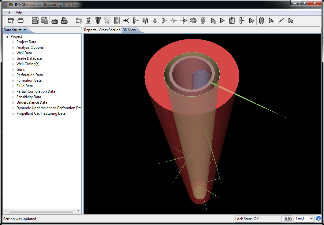
Perforation Prediction
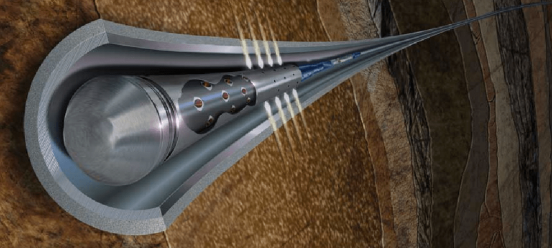
RETINA stimulation™ penetration and entrance-hole diameter calculations are based on API section 1 and Berea slab experiments. All Berea penetrations are calculated from Section 1 via a curve fit to the related data. This data is then adjusted, using classical penetration theory. All penetration and entrance-hole computations are made assuming the shaped-charge jet impacts normal to the casing/cement/formation. Experimental data has been obtained in most cases to calculate entrance-hole diameter and penetration for large clearances. The flow of modifications performed on API sections to calculate formation penetration is presented here:
.PNG)
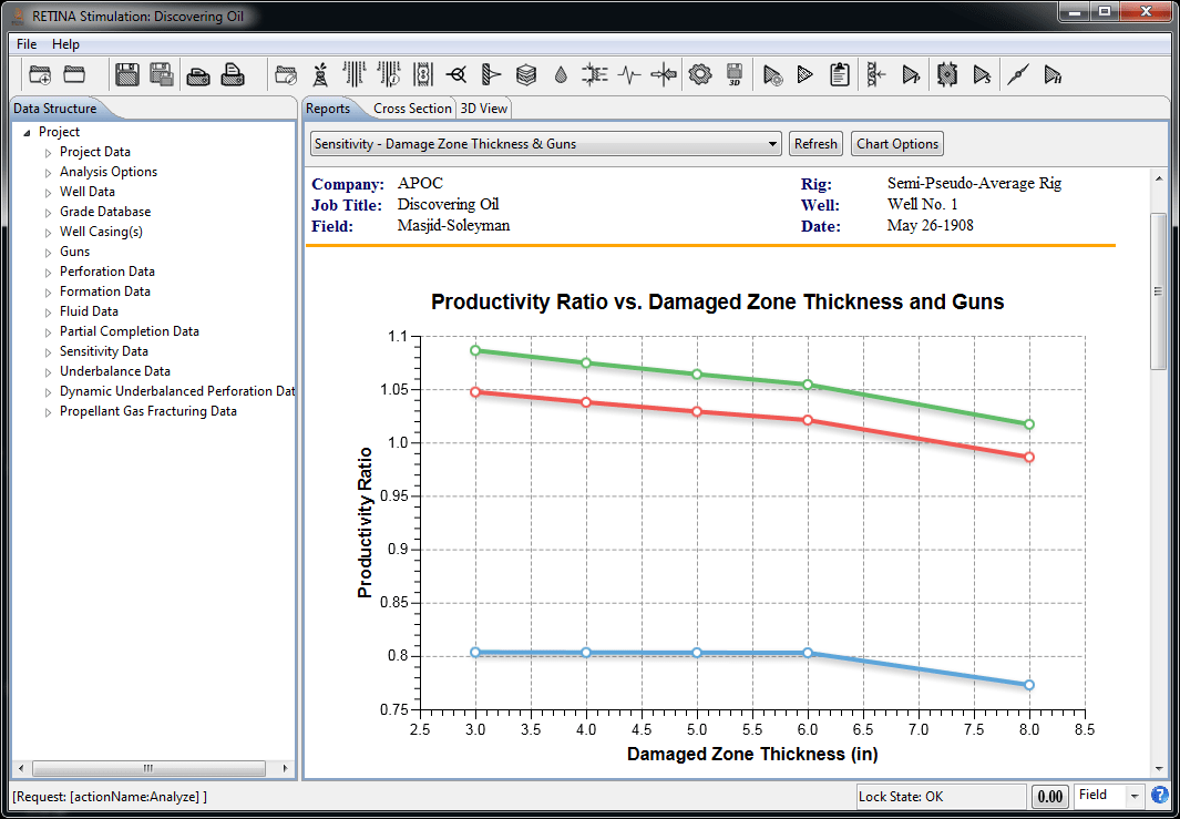
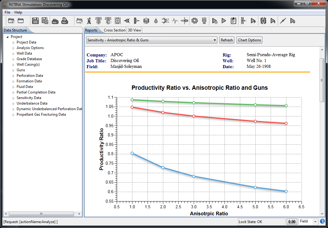
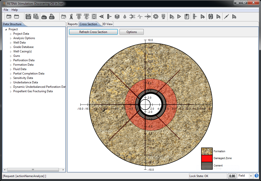
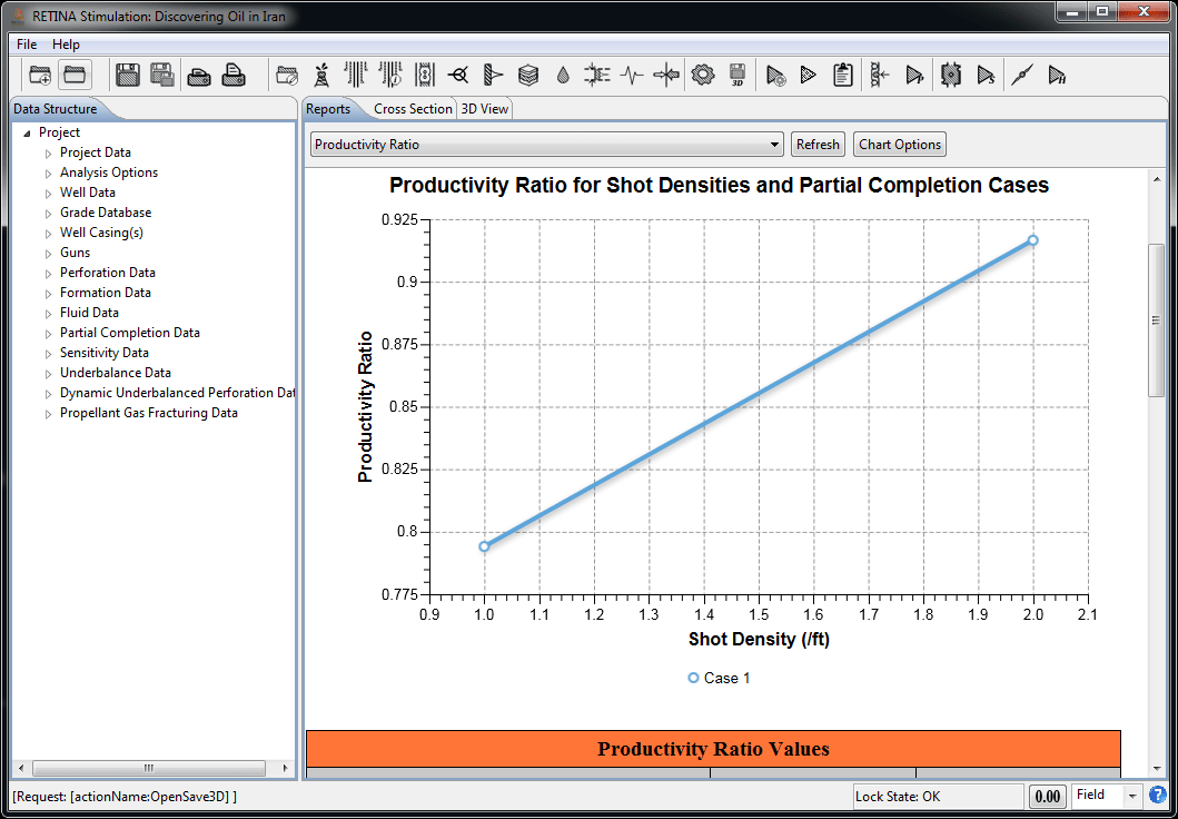
Productivity
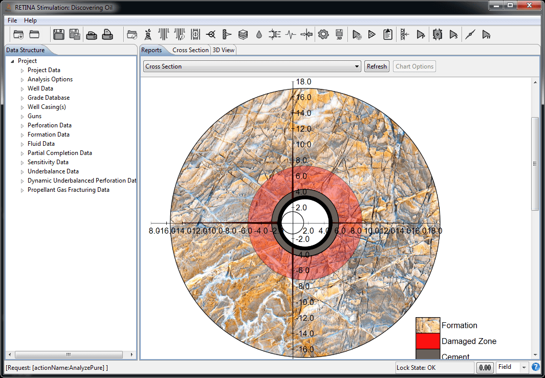
Productivity Ratio (PR) is a measure of the perforated completion efficiency relative to the ideal open-hole completion (Damage Skin=0). In reality, the penetration patterns are nonsymmetrical. So, productivity ratios for each perforation tunnel will be different based on its length and diameter. No productivity ratio is calculated for charges that do not penetrate the formation. Productivity ratio is a good theoretical measure for the efficiency of a completion, however, the pseudo-steady-state Productivity Index (PI) and Flow Efficiency (FE) for the non-Darcy cases are also calculated. The user can perform sensitivity analysis on Productivity Index, Productivity Ratio, and Flow Efficiency.
Optimum Underbalance Pressure Prediction

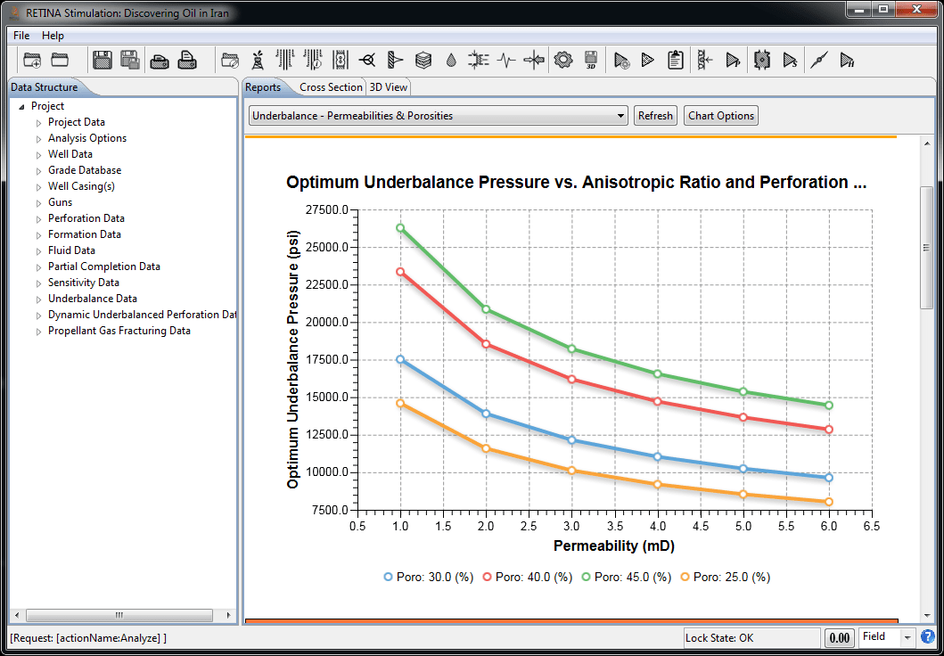
Assume that after the creation of the perforation tunnel there is only loose fractured sand (no liquid or high pressure gas) in the tunnel, so a differential pressure boundary condition exists at the tunnel walls equal to the reservoir pressure. A decompression wave moves radially from the tunnel wall, reducing the reservoir pressure. This pressure reduction is a function of the fluid and rock properties. If the pressure reduction at any given radius is fast enough, then a substantial pressure differential across a fractured sand grain can be developed. These calculations are based on equations developed on the basis of traditional static underbalance perforation theory.
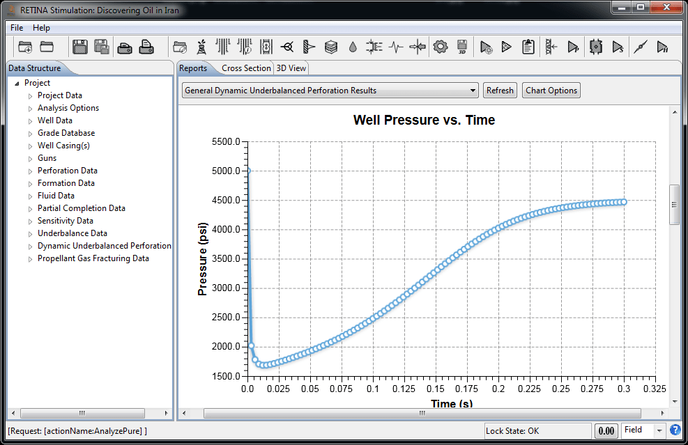
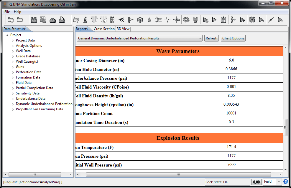
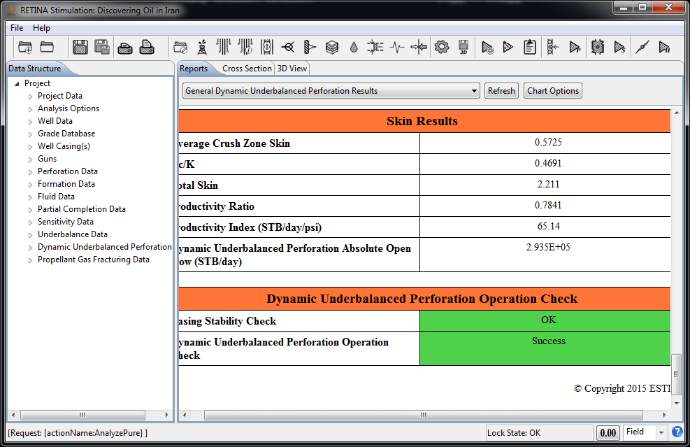
Dynamic Underbalanced Perforation
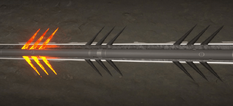
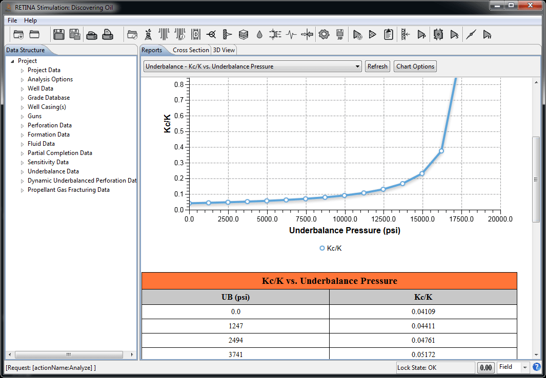
Recent research and field results indicate that a static underbalance pressure alone is insufficient to achieve clean perforations. So, a dynamic underbalance technique is designed to achieve an underbalance pressure immediately after perforation occurs. This can provide perforations with a very high kc/k ratio and larger tunnel diameter which, is the preferred method of perforation job design. There are five main calculation steps in modeling of this technique:
- - Detonation released gas volume
- - Gun internal temperature calculations
- - Remaining gas and energy amount in the gun
- - Gun internal pressure calculations and casing stability analysis
- - Skin calculations
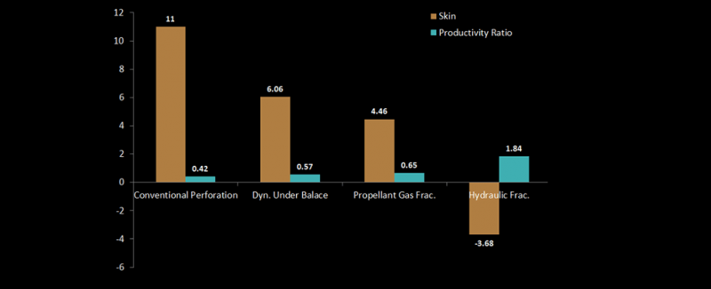
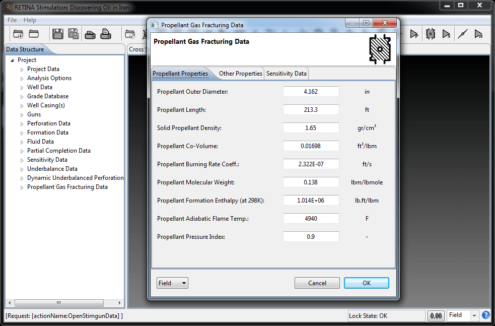
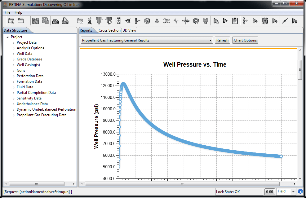
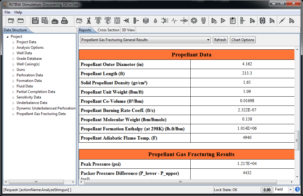
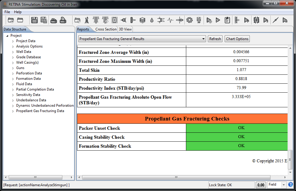
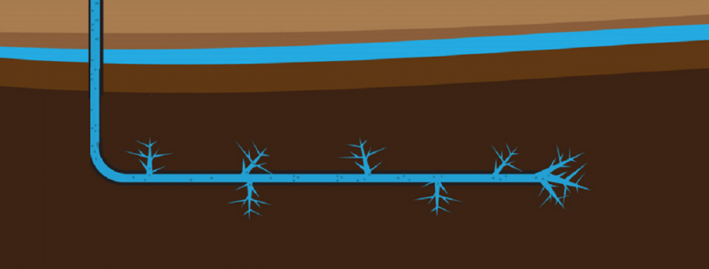
Propellant Gas Fracturing
"Propellant Gas Fracturing” is a technique that makes use of fast burning chemicals in wells to fracture the formation near the wellbore and stimulate the well productivity or injectivity. The process of propellant gas fracturing normally takes less than one second. Because of the compressibility of gas and the highly dynamic behavior of the process, the pressures in the charging canister (if the cased propellant-charge is employed ), the wellbore and the fractures vary with time and position. The geometric combustion law governs the flame propagation into propellant solid. This law applies until the propellant solid is burnt through and the main combustion is finished. The geometry of fractures initiated and propagated by propellant gas has been modelled as a set of wedge-shaped radial fractures with a constant height. In cased and perforated wells, the fractures are initiated in the same direction of perforations and are connected to the wellbore through perforations.
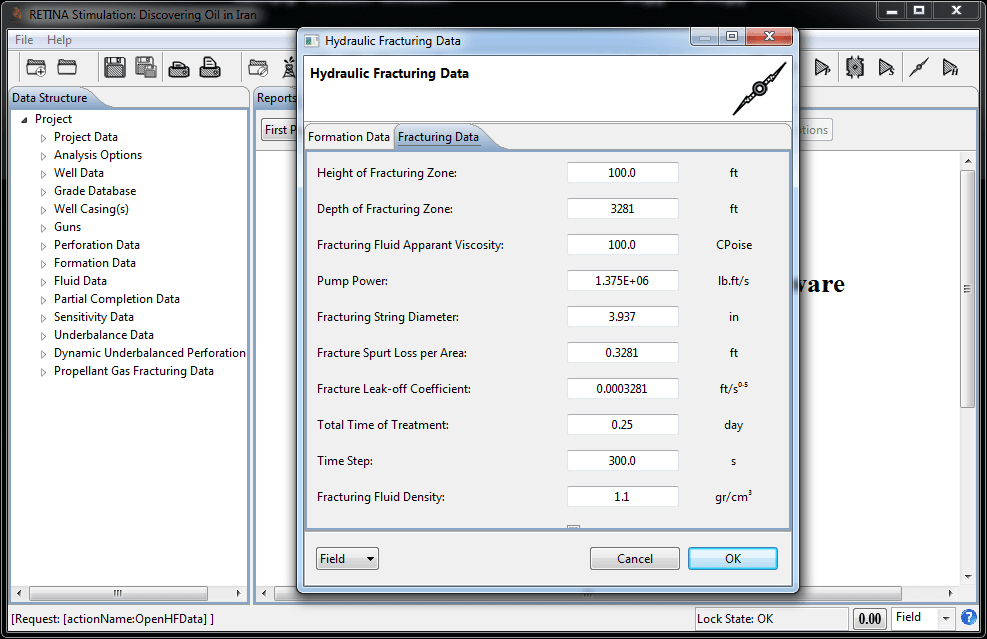
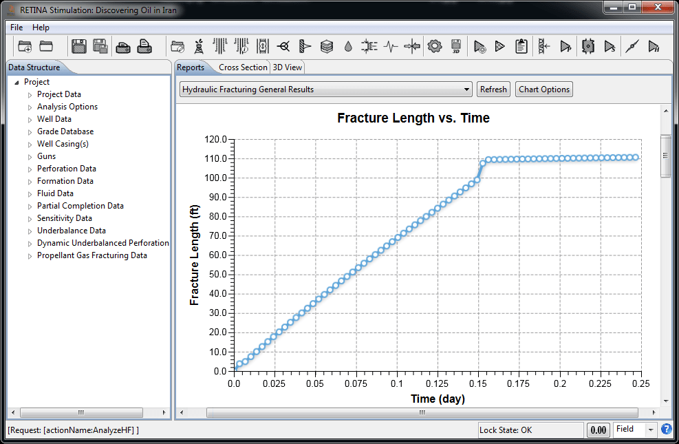
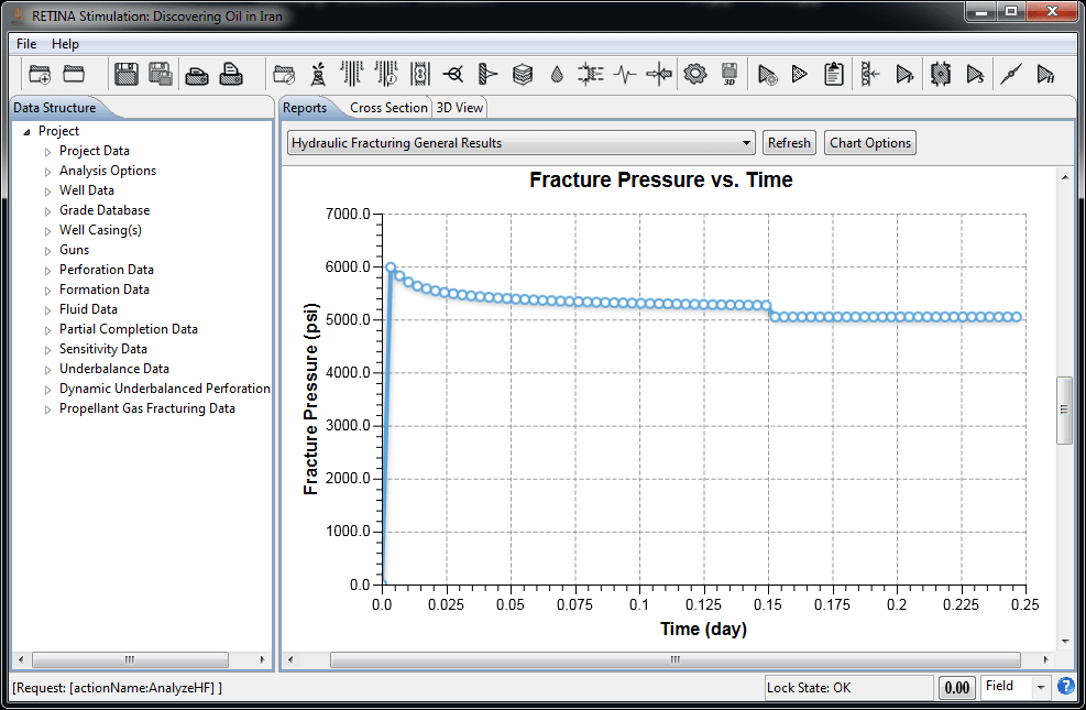
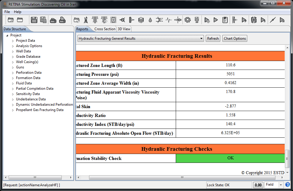
Hydraulic Fracturing
Wells in low to moderate-permeability reservoirs are candidates for hydraulic fracturing as a means of stimulating their performance. Like any other method of well stimulation, hydraulic fracturing, adjusts the skin effect (or the related effective wellbore radius). Hydraulic fractures bypass the near-wellbore damage zone. Modeling of hydraulic fracturing employs three fundamental equations of continuity, momentum (Fracture Fluid Flow) and LEFM (Linear Elastic Fracture Mechanics). The three sets of equations need to be coupled to simulate the propagation of the fracture. The material balance and fluid flow are coupled using the relation between the fracture width and fluid pressure. The resulting deformation is modeled through LEFM. Two models of "Perkins-Kern-Nordgren (PKN)” and ” Geertsma-de Klerk (GDK) ” both including non-Newtonian fluid effects and leak-off from the face of the fracture normal to the formation are used for dynamic fracture propagation and hydraulic fracturing design.